
GST : 27AAFFV7667M1ZA

call images

Call us

08045801431

7 Tips for Barite Drywall Radiation Shielding?

Radiation shielding decisions should begin with evidence, not attractive wall panels. Barite Drywall Radiation Shielding can reduce scattered X-ray exposure when designed, installed, and verified correctly. However, no single board thickness suits every room. Equipment type, workload, beam direction, occupancy, distance, and wall construction all matter.

NCRP Report No. 147 provides widely used guidance for diagnostic X-ray facility shielding design. It emphasizes workload, use factors, occupancy, and controlled dose limits. The IAEA’s Safety Reports Series No. 47 also recommends formal shielding calculations and qualified expert review. These documents support a practical lesson: product labels cannot replace a radiation protection assessment. A dense barite panel may appear substantial, yet joints, doors, ceilings, service penetrations, and poorly sealed edges can create weak points. Small gaps matter.

Real rooms reveal the risks. A busy CT suite may produce a very different shielding demand from a low-use dental room. Nearby offices, corridors, and waiting areas also require attention. The National Council on Radiation Protection and Measurements promotes optimization under the ALARA principle, keeping exposure as low as reasonably achievable without compromising clinical work. That principle should guide every tip in this article.

Some assumptions deserve challenge. Barite drywall is not automatically safer than every alternative. It may simplify installation, but its mass can affect framing, transport, and structural loading. Verification is essential. A qualified medical physicist should review drawings, calculate shielding, and support post-installation radiation surveys. These seven tips focus on practical details, credible documentation, and the mistakes that are easy to overlook. Good shielding is quiet, measurable, and deliberately engineered.
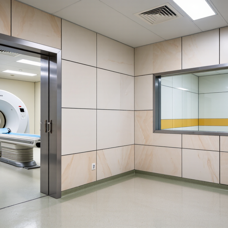
7 Tips for Barite Drywall Radiation Shielding?

Define X-Ray Energy, Workload, Distance, and Occupancy Before Shielding Design

7 Tips for Barite Drywall Radiation Shielding

Tip 1: Define the X-ray energy before selecting barite drywall. Diagnostic systems commonly operate across approximately 40–150 kVp, and higher energies require different attenuation assumptions.

Tip 2: Confirm the workload in mA-minutes per week. NCRP Report No. 147 identifies workload as a core shielding input, not a minor estimate.

Tip 3: Separate routine workload from peak clinical demand. A busy room can change quickly.

Tip 4: Measure distance from the X-ray focal spot to nearby occupied areas. The inverse-square relationship strongly affects shielding requirements.

Tip 5: Map occupancy carefully. A continuously occupied office differs from a corridor or storage room. IAEA Safety Reports Series No. 47 recommends evaluating distance, workload, radiation energy, and occupancy together.

Tip 6: Check primary and secondary barriers separately. The wall receiving the direct beam usually needs more attention than a scatter-only partition. Small design errors become expensive later.

Tip 7: Verify the installed construction, not only the drawings. Barite board joints, penetrations, doors, and service outlets can create weak points. Field surveys should follow commissioning and altered workloads. NCRP guidance supports design goals based on the protection of workers and the public. Still, published factors are not universal answers. Local measurements, equipment specifications, and a qualified medical physicist remain necessary. I sometimes see projects over-shielded because occupancy was guessed conservatively. That protects uncertainty, but wastes usable space and budget. A documented assumption is better than a hidden one.

Specify Barite Panels by Density, Thickness, and Lead Equivalence in mm Pb

7 Tips for Barite Drywall Radiation Shielding?

Specify Barite Panels by Density, Thickness, and Lead Equivalence in mm Pb

Barite drywall should never be specified by thickness alone. Start with panel density, usually reported in kg/m³, because heavier panels generally provide greater attenuation. Request the tested density, thickness, and declared lead equivalence in mm Pb. A 12 mm panel and a 20 mm panel are not interchangeable. Neither is a “high-density” claim without test evidence.

NCRP Report No. 147 and IAEA Safety Reports Series No. 47 emphasize workload, beam energy, distance, and occupancy when designing diagnostic imaging barriers. Their guidance does not support one universal shielding thickness. Ask for attenuation results at the relevant X-ray energies. Confirm whether the reported mm Pb value applies to the complete installed panel, including joints and fasteners. Small gaps can become practical weak points.

Use a continuous layout around doors, service penetrations, and wall-to-ceiling connections. Check panel weight against the supporting structure. Barite products can be surprisingly heavy. Require batch density records and independent laboratory reports, preferably with a clear test method and measurement uncertainty. I would not approve a panel based only on a brochure table. That is where specifications become fragile. Recheck the design with a qualified medical physicist, especially when room workload changes. A panel’s lead equivalence is a performance result, not a permanent material identity.

Calculate Required Thickness for 70–150 kVp Diagnostic X-Ray Rooms

Designing barite drywall for a 70–150 kVp diagnostic X-ray room requires more than matching a board to tube voltage. NCRP Report No. 147 recommends evaluating workload, use factor, occupancy, distance, and the shielding design goal. Its commonly applied goals are 0.1 mGy per week for controlled areas and 0.02 mGy per week for uncontrolled areas. Confirm local requirements with a qualified medical physicist. Rules vary.

Use this practical calculation path: define the weekly workload in mA-minutes, estimate the source-to-barrier distance, and assign use and occupancy factors. Calculate the transmission limit with B = P d² ÷ (W U T). Then convert B into required TVLs using n = log10(1/B). Multiply n by the barite board’s tested TVL at the selected kVp. Check seven details: board density, joint overlap, screw penetrations, door edges, ceiling height, adjacent occupancy, and primary-beam direction. Small gaps matter.

Barite drywall performance is not universal. Density, moisture, thickness, and installation quality can change attenuation. Reports from professional medical-physics groups warn against using lead-equivalent values without energy-specific testing. At 150 kVp, the beam is more penetrating than at 70 kVp. A single thickness may therefore be inadequate across the range. Measure twice. Do not guess. Keep calculation records, obtain supplier test certificates, and verify the finished room with a radiation survey. A shortcut may look efficient, but it can hide the weakest barrier.

7 Tips for Barite Drywall Radiation Shielding

Indicative barite drywall thickness ranges for 70–150 kVp diagnostic X-ray rooms

1. Confirm the tube voltage

Higher kVp produces a more penetrating beam and normally requires greater shielding performance.

2. Calculate the workload

Use weekly mA·min, examination frequency, beam direction, distance, occupancy, and the required design dose limit.

3. Verify the material

Barite density, board composition, joints, fasteners, penetrations, and installation quality affect the final shielding result.

The chart shows preliminary planning bands, not code-mandated values. The ranges assume typical diagnostic radiography, approximately 1 m occupied distance, moderate workload, and barite-based drywall with an approximate density of 2.8–3.2 g/cm³. Final thickness must be calculated and approved by a qualified medical physicist using the applicable shielding standard, workload, occupancy, distance, and design goal.

Seal Joints, Penetrations, Doors, and Openings to Prevent Radiation Leakage

7 Tips for Barite Drywall Radiation Shielding

Barite drywall works only when the entire barrier remains continuous. Seal panel joints tightly, and stagger seams between layers. Keep screw heads covered with compatible shielding compound. Small gaps can become practical leakage paths. They are easy to miss.

Control seven weak points during installation: panel joints, floor lines, ceiling connections, cable penetrations, pipe sleeves, doors, and service openings. Overlap or sleeve penetrations with matching shielding material. Do not place electrical boxes back-to-back. Shield door frames continuously, and verify that the door closes firmly against its seals. A heavy door is not automatically a safe door. Site experience shows that rushed finishing often creates the most avoidable defects.

Shielding thickness must follow a qualified medical physicist’s calculation. NCRP Report No. 147 bases design on workload, beam energy, distance, occupancy, and use factors. IAEA Safety Reports Series No. 47 also emphasizes primary barriers, secondary barriers, and construction details. These reports support design decisions, but they do not replace a room-specific assessment. Before occupancy, inspect every joint and penetration under suitable lighting. Record photographs and repair locations. Radiation surveys should confirm the completed installation. A clean-looking wall can still fail at a hidden sleeve. That possibility deserves attention.

Verify Installation with Radiation Surveys and Applicable NCRP or IAEA Limits

Barite drywall shielding should be verified, not assumed. A finished wall can look solid while seams, outlets, door frames, and service penetrations create weak points. After installation, a qualified radiation protection professional should survey adjacent rooms, corridors, offices, and occupied areas. Use a calibrated, energy-appropriate survey meter, record background readings, and test during representative clinical workloads. Small details matter. A two-centimeter gap can matter more than a perfect wall panel.

NCRP Report No. 147 emphasizes shielding design based on workload, beam energy, distance, and occupancy. Its recommendations are design tools, not automatic proof of compliance. IAEA General Safety Requirements Part 3 identifies a 1 mSv annual effective dose limit for members of the public and an occupational limit of 20 mSv per year averaged over five years, subject to applicable national rules. These figures must not be applied blindly. Survey results should be converted to realistic weekly or annual exposure estimates, using occupancy and operating schedules. Compare them with the approved design goals and local regulatory requirements. Keep signed survey records, instrument calibration certificates, room layouts, and corrective actions. Recheck after equipment replacement or workload changes. We sometimes trust drawings too much. That is a mistake worth correcting.

7 Tips for Barite Drywall Radiation Shielding? - Verify Installation with Radiation Surveys and Applicable NCRP or IAEA Limits

No. Shielding Tip Recommended Action Relevant Data or Acceptance Check Reference Basis
1 Start with a documented shielding design Define the radiation source, maximum operating voltage, workload, use factor, occupancy factor, adjacent areas, and design dose constraints before selecting barite drywall thickness. A shielding calculation should identify the source-to-barrier distance and the areas protected by each barrier. Thickness alone is not a universal performance value because attenuation depends on photon energy and material density. NCRP Report No. 147 and IAEA Safety Reports Series No. 47 provide diagnostic-radiology shielding design methodologies.
2 Confirm the material and installed density Keep delivery documentation and verify the specified barite-board type, nominal thickness, panel joints, and material density against the approved design. Record the measured or certified density in kg/m³, panel thickness in mm, and the locations where each product is installed. Do not substitute ordinary gypsum board without recalculating the design. Shielding performance is mass- and energy-dependent; product documentation and project specifications must control the acceptance criteria.
3 Eliminate gaps, joints, and penetrations Stagger board joints, tightly fit panels, seal service penetrations, and coordinate electrical, ventilation, plumbing, doors, and viewing windows with the shielding design. Inspect every joint and penetration before concealment. A gap, offset, or unshielded opening can create a localized radiation streaming path even when the main wall meets its nominal thickness. NCRP and IAEA shielding guidance emphasizes continuity of the barrier and control of radiation streaming through openings.
4 Protect doors, frames, and viewing windows Check that the door, frame, window, and wall assemblies provide compatible shielding and that the door closes fully without excessive gaps. Survey the center, edges, frame, threshold, hinges, latch side, and adjoining wall. Pay particular attention to interfaces where different shielding materials meet. Barrier surveys should cover all accessible locations, not only the center of the shielded wall.
5 Perform a post-installation radiation survey Use a calibrated, energy-appropriate radiation survey meter and test the room under representative operating conditions after construction is complete. Record background, test factors, source position, distance, instrument serial number, calibration status, measurement locations, and results in µSv/h or mSv/h. IAEA safety guidance recommends radiation monitoring and verification by competent personnel using suitable, calibrated instrumentation.
6 Compare results with the approved design goal and applicable limits Have the radiation protection expert or regulator determine whether measured values satisfy the project design constraint and local legal requirements. Common international reference values are:
  • Occupational effective dose: 20 mSv per year averaged over 5 years, with no single year exceeding 50 mSv.
  • Public effective dose: 1 mSv per year.
  • 1 mSv equals 1,000 µSv; 1 mSv equals 100 mrem.
These values are not a substitute for the project-specific shielding design goal or national regulations.
IAEA General Safety Requirements Part 3 and internationally used ICRP recommendations; NCRP design guidance may use occupancy-based constraints for specific facility conditions.
7 Document, correct, and re-survey If any location exceeds the approved criterion, stop acceptance, investigate the cause, repair or add shielding, and repeat the survey before clinical use. The final record should include a floor plan with measurement points, survey date, equipment settings, measured values, background readings, corrective actions, and reviewer approval. A documented commissioning survey provides traceability and supports ongoing radiation-protection quality assurance.
Important: Radiation shielding requirements depend on the equipment, workload, beam energy, room layout, occupancy, distance, applicable national regulations, and the approved design calculations. NCRP and IAEA publications should be applied by a qualified medical physicist or radiation-protection expert.
Back to top
