
GST : 27AAFFV7667M1ZA

Call us
08045801431
Call us
08045801431

Choosing the right NTC Temperature Probe begins with the application, not the catalogue image. A probe touching a stainless-steel pipe behaves differently from one measuring air inside a refrigerator. Response time, resistance tolerance, temperature range, cable length, insulation, and mounting pressure can change the final reading.
Industry data shows why this choice matters. MarketsandMarkets identifies thermistors as important components in automotive, medical, industrial, and consumer electronics sensing systems. Its recent thermistor market analysis also points to continued demand for compact, accurate temperature devices. Grand View Research reports similar growth across temperature-sensor applications, especially in electric vehicles, battery systems, and connected equipment. These reports describe market direction, not a guarantee of performance.
Small details decide accuracy.
As sensor engineer John R. Vig has emphasized, “A measurement is only meaningful when its uncertainty is understood.” That principle applies directly to every NTC Temperature Probe selection. A tightly specified resistance curve may still deliver poor results when the probe is poorly positioned. In practical testing, a probe pressed against a cold metal wall can report a misleading value within seconds.
The ten tips in this guide examine those decisions closely. They cover Beta value, Steinhart–Hart coefficients, interchangeability, waterproofing, response speed, connector design, calibration, and long-term stability. Some choices remain imperfect. A faster probe may sacrifice durability. A stronger cable may reduce flexibility. The cheapest option can become expensive after recalibration and replacement.
Measure the real environment first. Then compare specifications that reflect it.
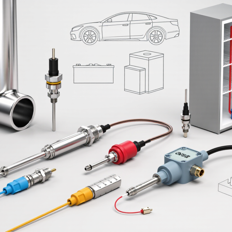
Understanding NTC temperature probe basics starts with one simple fact: its resistance falls as temperature rises. This negative temperature coefficient allows precise sensing through a voltage divider or measurement circuit. The resistance-temperature curve is not linear, so engineers often use the Beta equation or Steinhart-Hart equation for conversion. IEC 60539-1 defines key requirements for directly heated NTC thermistors. Its guidance supports careful attention to resistance tolerance, Beta-value tolerance, and long-term stability.
The probe’s physical design matters just as much. A stainless-steel sheath protects the sensing element, while epoxy sealing improves moisture resistance. Thin probes usually respond faster, but they may suffer more from mechanical stress. Self-heating is another quiet problem. Excessive measuring current can warm the element and create a falsely low temperature reading. A perfect-looking reading can still be wrong. The IEA’s Energy Efficiency 2023 report estimates that buildings consume about 30% of global energy demand, making dependable temperature feedback important for heating and cooling control.
Tip: Match the probe’s resistance at 25°C with your controller. Check the Beta value, not only nominal resistance. Select a small thermal mass for faster response. Test the finished assembly in an ice bath and a controlled warm bath. I would also question impressive accuracy claims without tolerance curves, response-time data, and calibration conditions. Cable length, connector resistance, and airflow can shift real-world results. Even installation depth matters. A probe touching a metal wall may measure the wall, not the surrounding air.
| No. | Selection Dimension | What to Check | Relevant Technical Data | Why It Matters |
|---|---|---|---|---|
| 1 | Define the Measurement Range | Choose a probe whose rated operating range covers the complete expected temperature range, including short-term extremes. | Typical NTC probe applications may range from approximately -50°C to +150°C, while the actual limit depends on the sensing element, insulation, cable, seal, and housing. | Operating outside the specified range can cause drift, insulation damage, moisture ingress, or permanent loss of accuracy. |
| 2 | Select the Nominal Resistance | Match the probe resistance at the reference temperature to the input range of the controller, meter, or measurement circuit. | Common reference values at 25°C include 2.252 kΩ, 5 kΩ, 10 kΩ, and 100 kΩ. The 10 kΩ value is widely used, but it is not universal. | A resistance mismatch can reduce resolution, create calibration errors, or prevent the electronic circuit from recognizing the sensor correctly. |
| 3 | Verify the B-Value | Compare the thermistor’s beta value and reference temperatures with the values used in the controller software or calculation model. | The beta value is commonly specified between 25°C and 50°C or between 25°C and 85°C. Typical NTC values may be approximately 3,000–5,000 K. | The B-value determines how resistance changes with temperature. An incorrect value can produce significant temperature-reading errors. |
| 4 | Check Accuracy and Interchangeability | Review the resistance tolerance, temperature accuracy, calibration points, and interchangeability requirements of the application. | Accuracy is application-specific. A probe may be specified by resistance tolerance at 25°C, temperature accuracy at selected points, or a complete resistance-versus-temperature curve. | Resistance tolerance and beta-value tolerance both affect the final temperature error; checking only one specification is insufficient. |
| 5 | Match the Probe Construction | Choose the sensing tip, metal tube, threaded fitting, surface mount, or flexible cable style that suits the installation location. | Common constructions include Stainless-steel probe Epoxy-coated bead Ring terminal Surface sensor | The mechanical design affects response time, durability, installation access, and the amount of thermal contact resistance. |
| 6 | Assess Response Time | Use the response-time specification under conditions similar to the real application, such as still air, moving air, liquid, or a metal surface. | Response time is commonly stated as time constant τ, the time required to reach approximately 63.2% of a step change in temperature. | A smaller probe and better thermal contact generally provide faster response, but may reduce mechanical protection or increase sensitivity to installation conditions. |
| 7 | Evaluate Environmental Protection | Check resistance to water, condensation, dust, chemicals, vibration, pressure, and repeated temperature cycling. | Look for an appropriate enclosure or ingress-protection rating, such as IP65, IP67, or IP68, when the application requires protection from dust or water. The rating must apply to the complete assembled probe. | Ingress protection is important because moisture and contamination can change insulation resistance and create unstable readings. |
| 8 | Choose the Cable and Insulation | Confirm cable length, conductor size, flexibility, bend requirements, temperature rating, chemical compatibility, and shielding needs. | Cable insulation may use materials such as PVC, silicone, or PTFE. The cable temperature rating must be at least as high as the actual installation temperature. | The cable is often the limiting component. Insulation softening, embrittlement, leakage, or poor strain relief can cause premature failure. |
| 9 | Consider Self-Heating | Keep the measuring current low enough that the electrical power dissipated by the thermistor does not noticeably raise its temperature. | Self-heating power is calculated as P = I²R. The resulting temperature rise depends on the thermistor’s dissipation factor and the surrounding medium. | Excessive measuring current can make the probe read higher than the actual temperature, especially in still air or other poorly dissipating environments. |
| 10 | Confirm Testing and Compatibility | Verify connector compatibility, wiring configuration, calibration method, mechanical fit, and required inspection or qualification tests. | Useful checks include resistance at known temperatures, insulation resistance, continuity, dimensional inspection, thermal cycling, vibration testing, and leak testing where applicable. | Testing the complete probe and its installation helps identify wiring, sealing, calibration, and assembly problems before field deployment. |

 Send Inquiry

