
Selecting an ACB Breaker for global power systems requires more than comparing interrupting ratings. Engineers must examine voltage levels, prospective short-circuit currents, ambient temperatures, installation altitude, and maintenance capabilities. A breaker that performs reliably in a European data center may need different settings in a humid coastal plant or a high-altitude mine.
Dr. Arun K. Sharma, a power-distribution engineer with extensive low-voltage switchgear experience, states, “An ACB earns trust when its protection settings match the real network, not merely the catalogue.” This practical view reflects the purpose of IEC 60947-2: equipment must be evaluated within its intended electrical conditions. It also reminds designers that certification alone does not guarantee a suitable installation.
An ACB Breaker offers several advantages for international projects. Its adjustable long-time, short-time, instantaneous, and earth-fault protection can support coordination across complex distribution boards. Withdrawable designs can simplify inspection and replacement. Electronic trip units may also provide event records, helping maintenance teams investigate overloads before damage spreads.
Yet the choice is not automatically correct. A sophisticated breaker can fail to deliver value when settings are poorly calculated or maintenance access is ignored. Small details matter. Cable length matters. Dust matters. Human judgment still matters.
Global projects also face inconsistent documentation, local practices, and supply-chain limitations. Engineers should verify type-test evidence, spare-part availability, installation clearances, and after-sales support. A careful selection process may take longer, but it reduces nuisance trips, unplanned downtime, and unsafe troubleshooting. There is no perfect universal solution. The strongest decision connects proven technology with the actual behavior of the power system.
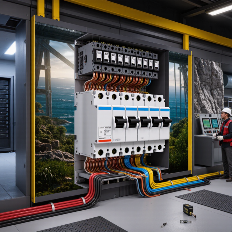
Why Choose an ACB Breaker for Global Power Systems?
An ACB, or air circuit breaker, protects low-voltage distribution boards by interrupting fault current in air. During normal operation, fixed contacts carry load current with limited voltage drop. When a short circuit appears, sensors detect abnormal current. An electronic trip unit then commands the mechanism to open. Arc runners and splitter plates divide, cool, and extinguish the arc. Air does the work.
That sequence is simple, but coordination is not. Trip settings must match cable capacity, transformer impedance, and downstream breaker curves. Otherwise, a feeder fault may disconnect an entire floor. IEC 60947-2 defines important requirements, including rated performance, testing, and short-circuit verification. Engineers should compare Icu, Ics, short-time withstand current, and endurance ratings with the installation study. These values are not interchangeable.
Global demand makes this discipline more important. The IEA Electricity 2024 report expects electricity demand to grow by an average 3.2% annually from 2024 to 2026. Its Renewables 2024 report also forecasts around 5,500 GW of new renewable capacity by 2030. More sources create more switching and protection challenges. ACBs offer adjustable protection, high current capacity, and practical isolation for large boards. Draw-out designs can simplify inspection and replacement. Field commissioning often reveals one weakness: settings are copied instead of calculated. That assumption fails. An ACB is not automatically the best choice. It can be oversized, expensive, or poorly coordinated without a careful study.

In global power systems, safety begins with controlled interruption. An air circuit breaker (ACB) can detect overloads, short circuits, and earth faults. It then disconnects dangerous current before conductors overheat. Modern electronic trip units also support adjustable protection settings. This matters across factories, hospitals, data centers, and renewable-energy installations. Conditions vary widely.
The IEC 60947-2 standard defines key requirements for low-voltage circuit breakers. These include rated short-circuit performance, temperature limits, and testing procedures. Selective coordination is equally important. It allows the nearest protective device to operate first, keeping healthy circuits energized. In practice, poor settings can defeat good equipment. A powerful ACB is not automatically a safe one.
The NFPA report Home Fires Caused by Electrical Distribution and Lighting Equipment, covering 2016–2020, recorded about 32,000 U.S. home fires annually. Those fires caused approximately 470 deaths, 1,100 injuries, and 1.3 billion dollars in property damage each year. The figures are not global, but they show the cost of electrical failure. Arc-flash reduction, visible isolation, undervoltage protection, and remote operation can reduce exposure during maintenance. Still, these functions require accurate studies, regular testing, and trained technicians. It sounds obvious. Yet maintenance gaps remain common.
Why Choose an ACB Breaker for Global Power Systems?
Electrical Ratings, Standards, and Regional Compatibility
An air circuit breaker must match the system, not merely the panel space. Its key ratings include rated current, operational voltage, frequency, and short-circuit breaking capacity. Engineers should also compare Icu and Ics values under IEC 60947-2. Icu indicates ultimate fault interruption. Ics reflects service-level performance after fault testing. These figures affect safety, maintenance, and replacement planning.
According to the IEA Electricity 2024 report, global electricity demand is expected to grow by an average 3.4% annually from 2024 to 2026. More demand increases pressure on distribution equipment. An ACB with adjustable protection can support changing loads, generators, and parallel feeders. However, adjustment is not a substitute for a verified coordination study. A neat rating table can still mislead.
Regional compatibility requires careful document checks. IEC-based projects commonly use IEC 60947-2, while North American installations may require UL 489 and CSA C22.2 No. 5. China-based projects often reference GB/T 14048.2. Voltage, frequency, interrupting ratings, terminal designs, and certification marks can differ. Even a 60 Hz breaker may be unsuitable for a 50 Hz application. Small details matter.
Check the local authority.
Project teams should verify test certificates, temperature derating, altitude limits, and installation clearances. Some specifications remain incomplete. That deserves review, not assumption. A reliable selection records the fault level, enclosure conditions, required accessories, and regional approval path before procurement.
An air circuit breaker supports global power systems because it combines high interrupting capacity with accessible inspection points. Installation quality determines much of its future performance. Busbars should align without forcing the terminals, while joint torque must follow the equipment specification. Poor torque can create hot spots that remain invisible during normal operation. Protection settings also require coordination studies, not guesswork. IEC 60947-2 provides the relevant low-voltage circuit-breaker framework.
The pressure is increasing.
The International Energy Agency’s Electricity 2024 report projects global electricity demand growth of about 3.4% annually through 2026. Higher loads make thermal scanning, insulation checks, and trip testing more important. Maintenance teams should record contact wear, operating counts, temperature trends, and fault history. A fixed calendar is useful, but it is not enough. Dust, humidity, vibration, and switching frequency change the real interval. Keep critical spare mechanisms and trip units available.
Downtime is expensive.
Uptime Institute’s Annual Outage Analysis 2024 found that 54% of reported outages caused more than $100,000 in direct or indirect losses. That figure makes lifecycle planning practical, not theoretical. During inspections, technicians should verify mechanical operation, secondary wiring, and protection response. Digital records improve traceability across sites. Yet remote monitoring can create false confidence. Sensors need calibration, and alarms need human review. An ACB may last for decades, but only disciplined commissioning and evidence-based maintenance preserve that value.
Why Choose an ACB Breaker for Global Power Systems?
Comparing an ACB breaker with other protection devices starts with operating conditions. An ACB is designed for high-current, low-voltage switchboards. Its air-based arc interruption supports repeated switching and easier inspection. In field commissioning, engineers often value adjustable long-time, short-time, instantaneous, and ground-fault settings. These controls help match protection to transformers, generators, and downstream feeders.
An MCB suits smaller final circuits, such as lighting or office outlets. It is compact, economical, and usually has limited adjustment. An MCCB handles higher currents and offers stronger interruption capacity, but its frame size and settings vary widely. Fuses can clear severe faults quickly, although replacement after operation may delay restoration. RCDs and RCCBs focus on leakage protection, not complete overload coordination.
That difference matters.
An ACB also supports draw-out installation, visible isolation, mechanical interlocking, and communication accessories. These features can improve maintenance in hospitals, factories, and data facilities. However, an ACB is not automatically the safest choice. It needs careful setting studies, arc-flash assessment, routine testing, and trained operators. Poor coordination can still trip an entire bus section unnecessarily. I have seen specifications that emphasized interrupting capacity but overlooked cable thermal limits. That is an easy mistake. Local grid voltage, fault levels, installation rules, and maintenance capability should guide the final selection.
| Comparison Dimension | ACB (Air Circuit Breaker) | MCCB (Molded Case Circuit Breaker) | MCB (Miniature Circuit Breaker) | Fuse | RCBO |
|---|---|---|---|---|---|
| Typical rated current range | 630–6,300 A | 16–1,600 A | 0.5–125 A | From less than 1 A to several thousand amperes, depending on fuse type | 6–125 A |
| Typical system voltage | Up to 690 V AC in many low-voltage power systems | Up to 690 V AC in many industrial applications | Usually up to 240/415 V AC | Application-dependent; low-voltage AC and DC versions are widely available | Usually up to 240/415 V AC |
| Typical short-circuit breaking capacity | Approximately 42–100 kA, depending on frame size and configuration | Approximately 18–100 kA, depending on model and voltage | Approximately 6–25 kA | Approximately 10–200 kA, depending on fuse class and application | Approximately 6–25 kA |
| Primary protection role | Main incomers, bus-couplers, generators, transformers and high-current feeders | Distribution feeders, motors, transformers and medium-to-high current loads | Final circuits for lighting, sockets and small equipment | Overcurrent and short-circuit protection for feeders, equipment and specialized circuits | Overcurrent plus residual-current protection for individual final circuits |
| Overload protection | Electronic or thermal-magnetic trip units; long-time protection is commonly adjustable | Thermal-magnetic or electronic trip units; adjustment depends on design | Thermal-magnetic protection with fixed or limited settings | Provided by the fuse element through its time-current characteristic | Thermal-magnetic overcurrent protection |
| Short-circuit protection | Magnetic or electronic instantaneous protection; short-time delay may support selectivity | Magnetic or electronic instantaneous protection; some units provide short-time delay | Magnetic instantaneous protection with standard B, C or D tripping characteristics | Very fast current-limiting action is available with suitable fuse designs | Magnetic instantaneous protection combined with residual-current protection |
| Residual-current protection | Usually requires a separate residual-current relay or compatible integrated module | Usually requires a separate residual-current device or relay | Not normally included | Not provided by the fuse element alone | Integrated residual-current protection, commonly available at 30 mA for personal protection |
| Reset or replacement after operation | Resettable after inspection; no fuse replacement is required | Resettable after inspection; no fuse replacement is required | Resettable after inspection; no fuse replacement is required | Fuse replacement is required after operation | Resettable after inspection; no fuse replacement is required |
| Selectivity and coordination | Strong capability with adjustable time-current settings, zone-selective interlocking and communication options | Good capability when coordinated with upstream and downstream devices; depends on available settings | Limited adjustment; coordination is mainly achieved through device selection and rating | Can provide excellent selectivity when correctly selected using manufacturer time-current curves | Coordination depends on both overcurrent and residual-current characteristics |
| Remote operation and monitoring | Common options include motor operators, shunt trips, undervoltage releases, auxiliary contacts and communication modules | Available on many industrial models, but generally with fewer control and monitoring functions than an ACB | Available on selected modular systems; normally limited compared with ACBs | Requires separate switching, monitoring or control equipment | Available on selected smart or accessory-equipped designs |
| Maintenance requirements | Periodic inspection, cleaning, mechanical checks and trip-unit testing are recommended for critical installations | Generally lower maintenance than an ACB, but inspection and testing remain necessary in critical systems | Usually low maintenance; replacement may be preferred after severe fault duty | Requires correct replacement, inspection of holders and verification of spare-fuse ratings | Periodic functional testing of residual-current operation is recommended |
| Physical installation | Larger draw-out or fixed-frame equipment; requires suitable switchboard space and busbar connections | Compact fixed or plug-in construction; suitable for distribution boards and motor-control assemblies | Compact modular DIN-rail installation | Fuse holders, switch-fuse units or fuse panels are required | Compact modular installation, typically on a DIN rail |
| Operational continuity | High suitability for critical systems because it can be reset, tested and integrated into transfer or distribution schemes | Suitable for most industrial distribution systems with appropriate coordination | Suitable for non-critical final circuits and small distribution loads | Fast fault clearing, but continuity is interrupted until the fuse is replaced | Suitable for circuits requiring both overcurrent and earth-leakage protection |
| Best-fit application | Large commercial buildings, data centers, industrial plants, utilities, generators and low-voltage main switchboards | Industrial feeders, motor control centers, commercial distribution and high-current branch circuits | Residential, commercial and light-industrial final circuits | High fault-current locations, semiconductor protection, motor circuits and applications requiring current limitation | Individual circuits where electric-shock and leakage-current protection are required together with overcurrent protection |
| Common international reference standards | IEC 60947-2; local installation rules and switchboard standards may also apply | IEC 60947-2; local installation rules may also apply | IEC 60898-1 for household and similar applications; IEC 60947-2 for certain industrial applications | IEC 60269 series; the applicable fuse category depends on the application | IEC 61009-1 for residual-current circuit-breakers with integral overcurrent protection |
For an immediate response, please call this
number08045801431
Price:
